


Energy Storage tied to Smart Grid Solar Array
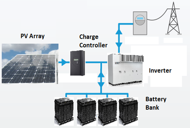
DC Coupled PV and Storage System
Key development objectives for the Hartsel Springs Solar Ranch (HSSR) project were for the system to: 1) provide the lowest levelized cost of energy (LCOE), 2) provide reliable dispatchable power based on utility signals, 3) make the most efficient use of solar energy, and 4) utilize proven equipment sets in order to attract investments and be bankable. For this project, one decision point that had major ramifications across the entire project design was between using AC and DC coupling architectures.
The initial selection of electrical topology of the collection grid, the architecture of the individual power blocks, and most importantly, how the proposed battery storage would be efficiently integrated into the photovoltaic system (PV) was crucial. Design iterations were performed around these two basic approaches: An AC-coupled system or a DC-coupled system. As the name implies, in a conventional AC-coupled system, the outputs of the PV and battery are coupled on the AC side of the system. In a DC-coupled system, the outputs of the PV and battery are coupled on the DC side of the system.
One of the most important attributes of grid-based energy storage is discharge duration flexibility. The HSSR energy storage system was designed not only have a wide range of discharge rate capability up to the peak amount, but it would also have an essentially flat storage capacity curve of between 2- to 7-hours. This storage and discharge efficiency would allow grid operators enhanced flexibility in maximizing storage economies. Since Xcel’s challenge was to provide only slightly more power than customers need at any particular moment in time, the HSSR system would provide the energy resource to mitigate peaks and valleys on a section of the distribution grid prone to fluctuations.
With AC coupling, single-stage inverters are used that convert DC to AC. For PV systems with storage, separate inverters are used for both the batteries and PV. As this is the most widely used topology there is a large commercial market for PV inverters of this type. Batteries are connected to the AC bus with bi-directional inverters, and similar to the PV inverters, these bi-directional inverters are single-stage and are commercially available.
DC coupling requires inverters that are not as commercially available as AC inverters since they require a fundamentally different inverter topology. For DC coupled systems, DC sources share a common bus, with the inclusion of a charge controller to modulate charging currents. Although there are fewer inverter choices with DC-coupled systems, these systems are more efficient when coupled, provided care is taken and proper electrical protection schemes are used. With DC coupling, the PV and batteries are paired on each inverter. For optimum utilization of electronics, this requires a unity between ratios of power output between the array and storage system. For the HSSR system, the sizing of the flow batteries was optimized for this reason within each power block.
Smart Grid Solar Reactive Power Support
The HSSR energy storage and voltage regulation systems were designed to dynamically support reactive voltage levels on the PSCo transmission line. The integrated energy storage systems and inverters were designed to provide the voltage support that was previously supplied by electrical generators, but at a much higher cost and greater challenge for PSCo. This is the case because it is typical to run extra electrical generators in the system to support grid voltage to ensure reliable service. However, with the dynamic VAR capability of a distributed smartgrid that incorporates 68 MWh of energy storage, utility dispatchers would be able to significantly scale-back the use of generators, which allows for a considerable reduction in operating fuel costs. The energy storage and dynamic VAR injection capability would provide additional benefits to the following
Feeder Relief
Transformer Bank Relief
Reactive Support for the T&D Grid
Remote Load Servicing
Power Quality Improvement
Peak Shaving
Load Growth & Ancillary Services
Loss Reduction
T&D Capital Expansion Defferal
Grid Asset Utilization Improvement
Advanced Battery Energy Storage Cornerstone of Smart Grid Solar System
The HSSR project proposed the use of energy storage for grid support as well as peak power shaving with the use of a transportable Advanced Battery Energy Storage System (ABESS). A unique aspect of this project was its modularity. The entire system was housed on a 40 x 8’ trailer, making it possible for the battery system to be used in multiple applications and locations. This pre-fabrication scheme would be deployed on each of the 34 1-MW AC solar modules.
The zinc-bromine flow battery has multiple advantages for utility energy storage applications. When connected to an electric power circuit known to have daily seasonal customer peak demand, the ABESS reduces peaks in the electrical load by adding energy to the circuit at predetermined conditions or times. When the peak use period passes, the system recharges using energy from the power grid during low-cost energy periods.
The designed power conditioning system (PCS) controls the charge and discharge of the battery to provide voltage stability to the end of a soft utility line during heavy line-loading by monitoring line voltage. Both VARs (volt-ampere reactive) and Real Power are provided at utility-controlled magnitudes ranging from zero to the rated capacity of the PCS. The PCS adjusts the reactive power to the line, as per the line voltage requirement or kVA demand signal through a communication link with the utility as an option. The PCS has functions of VAR power control and limiting real power in order to prevent the line voltage from increasing. If the VAR control is insufficient to prevent the line voltage from increasing, and when the line voltage exceeds a set value, the PCS limits the real power, depending on the available power form the Zinc Bromine Battery. In conditions where the line is high and the battery is not fully charged, the PCS draws active power to charge the battery and lagging VAR to stabilize the line. If the battery is fully-charged and cannot accept any real power, the PCS operates as a lagging VAR compensator only.
Energy Storage System Description
The HSSR energy storage system was based on a distributed grid of 2 MWh zinc-bromine flow batteries that could be utilized in a flexible smartgrid system for high power applications, as well as for high-capacity electricity storage. A flow battery is charged and discharged by a reversible chemical reaction between the two liquid electrolytes of the battery. These electrolytes are not stored in the power cell, as is the case with a conventional battery, but rather in separate storage tanks. During operation, these electrolytes are pumped through the electro-chemical reactor, in which a chemical redox reaction takes place and electricity is produced. Due to electrolyte storage outside the reactor, the specifications of the battery are flexible, and the power and energy content of the system can be separately specified. It is very easy to increase the amounts of electrolytes or replace them. Moreover, the design of the power cell can be optimized for the power rating needed, as this is independent of the amounts of electrolytes used.
Flow Battery Chemical Reactions

The zinc-bromine battery is very different in concept and design from more traditional batteries, such as lead-acid. Because it utilizes a circulation system to continuously feed reactants from external reservoirs into the battery stacks, it is classified as a “flowing electrolyte” or flow battery.
The stack consists of a series of bipolar electrodes and microporous separators between two monopolar (one negative and one positive) terminal electrodes. The bipolar electrodes allow the negative (zinc) reaction and positive (bromine) reaction to occur on opposite sides of the same electrode.
During charge, zinc is electroplated on the anode, and bromine is evolved at the cathode. A complexing agent in the electrolyte is used to reduce the reactivity and vapor pressure of the elemental bromine by forming a polybromide complex. This minimizes the self-discharge of the battery and significantly improves the safety of the system. The complexed bromine is then removed from the stacks via the flowing electrolyte and is stored in the external catholyte reservoir. On discharge, the complexed bromine is returned to the battery stacks, zinc is oxidized to zinc ions on the anodes, and bromine is reduced to bromide ions on the cathodes.

Fast-Acting Energy Storage
Assists Utility in Reliably Restoring Outages

Enhanced Integration of Renewables
Integrate renewable resources into standard operations, avoiding creation of more carbon gases
Defer Capital
Potential to defer significant capital infrastructure investments

Relief from Contingency Events
Utilize Transmission Full Thermal Limits
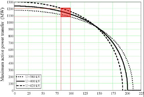
Enhanced ability for the interconnected transmission circuits to be loaded to full thermal limits as a result of the HSSR smart grid VAR compensation capability

Increased Security & Reliability
Inherent increased security and reliability due to the distributive and duplicative nature of the smart grid design (34 X 1 MWe)